


Last month my boss ask me to create a camera dolly track for photographing a time lapse movie. The system is designed to film my company’s construction project in Qishi Dongguan.
We wanted to make a time lapse movie with a DSLR during the assembly of the component based wood structure. Since the wood joints were CNC to correct fit, it should take 5 to 10 hours to assemble the whole 5 meter x 3 meter pavilion. The challenge for the camera track is that it needs to move the camera slowly and steadily along 3 to 4 meters, across 5 to 10 hours. Thus  the typically moving speed is 5 to 15 mm per minute.
For those who have no background knowledge on motors and motion: Typical commonly found DC (Toy Car) or AC motors (Electric Fan) spins at a fast revolution per minute (rpm) and the speed is a variable to the voltage your applied to the motor and the resistance from the load. There are no easy way to control the the speed of those motors precisely. (I’m omitting synchronized AC motors in this case, which is arguable difficult to control too)
The solution is obvious to use a stepper motor for creating the motion. I corroborated with Raymond Tong who is a machine consulting, who gave me great support on preparing the hardware. Since I have some experience in Arduino, the plan is to programme a stepper motor controller in Arduino, interface with a commercially bought stepper motor driver, driving a standard stepper motor hooked onto a timing belt, moving a cart forward and backwards.
I’m lazy to write a ‘instructable’, so I’ll casually share some experience here. I’m guessing Google will funnel who ever interested here.
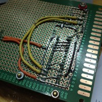
Arduino
The main challenge in this project is to programme an Arduino to receive input and control the motor. I have only three spare buttons in my tool box, so I decided that I’ll use them as the only inputs, this lead me to design a series of manual to do the following tasks. The center Red Button is the menu button, the left and right button are function keys:
- Run Programme (L: Run , R: Stop)
- Jog – Move the position of the dolly (L: Jog Left , R: Jog Right)
- Set Start/End – Set the current position of the dolly as start point or end point (L: Set Start, R: Set End)
- GotoStartEnd – Move the dolly to the start or end point (L: GotoSt, R: GotoEn)
- Set Time Hour (L: Minus, R: Add)
- Set Time Min (L: Minus, R: Add)
- Set Time Sec (L: Minus, R: Add)
- Info – check all settings
The normal operation of the system are
- Power up the system
- Jog the dolly to the user’s desired Start Position
- Set Start
- Jog the dolly to the user’s desired End Position
- Set Start
- Set the Hour/Min/Sec running time
- Increment the internal time value – recorded as a microsecond value (long), displayed as a H:M:S fomat.
- Move dolly to starting position if not already -Â GotoStart
- Run the programme (Current position in % and Remaining time will be displayed and updated constantly while running)
- Arduino will calculate the time between each step of the motor and step the motor through the driver
- Arduino will need to update the LCD display
- Arduino will need to check if user pressed the pause button
- Pause is possible while programme is running
- A buzzer will beep when the dolly reaches the end
- User can choose to reset the timer to the begining time at the end of the programme
Time sharing / pseudo OS on a micro controller
To do the above mentioned tasks, I realized that I cannot rely on conventional synchronous programming methods, which allowed only one process happening at one time. I have looked at using Schedulers and Pseudo Operating Systems. There are some nice schedulers library, particularly leOS is a good one, it is easy to use and simple to understand and control. The only problem is that it interfere with the LCD display library in a funny way, I had spend some time trying to figure out what happened, but I eventually gave up the OS. I suspect is that leOS might have interrupted the LCD library routine causing an incomplete data transmission to the LCD panel.
I also used the Bounce Library to read button input, it is not a very well documented library and examples are limited, I managed to make it work for my purpose, but don’t think I understand it completely.
At the time of writing the stepper controller, I have no idea how important a Stepper Library would be. I assumed that my stepper motor is going to run fairly slowly, so I might get away to writing my won stepping algorithm. This assumption is generally correct until I find that the Jog command cannot go very fast due to the lack of acceleration management. In this source code, I wrote my own stepping function, which is crude and barely functional, in future cases, I would recommend using a properly Stepper Motor Control Library such as AccelStepper. This is a nicely documented library and does not use interrupts on your micro-controller, controls acceleration and deceleration of as many steppers as you want. Supports stepper with micro-steps driver, 2, 3 and 4 wire steppers, plus 3 and 4 wire half steppers.
(Lesson learnt) Search for available libraries first before you dig into writting function yourself, other people might have already spent a lot of effort to solve a problem neatly. Especially on microprocessors, the language are rather low level language (consider that I first learn PHP and then VB.Net ), you don’t have a lot of spare processor time to waste if you wrote a clumsy logic to solve a problem.
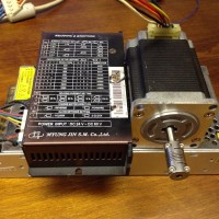
Stepper Motor Driver
I didn’t know that Stepper drivers are pretty easy to build from MOSFET components, so I bought a commercially available stepper driver from a second hand store (a new one would be about HKD150 – 300 for a 3A driver, depending on quality) . You can easily find them online too. Most of them feature micro-stepping, which is a great feature to improve the resolution of your stepper (Accuracy of the micro-steps is another topic).
They have built in current sensing ability. Meaning that you don’t need to worry the voltage of your motor (since most steppers are Current rated), you just need to set it to the right current. Note that in order for a stepper motor to have a constant current, it needs a higher voltage while it is spinning then stationary, faster it spins, higher the voltage. This is a vastly complex matter because in larger load situations (not my dolly), you will want to separately set the holding current (while motor is stationary) and running current, is nice to have a driver manages all that.
If you are completely cheap with all that, or want to experiment with building a simple stepper driver yourself, I am planning to make a separate post about that. What I mean simple is that does not feature all of the above mentioned current management ability. I’ll write that up when I have time.
(Lesson Learnt) I burnt my first stepper driver by using it to drive some unknown motors, probably I plugged a very small voltage high current motor to it, and setting the current to fairly high. So next time if I start a new motor driver combination, use a low current setting first.
Stepper Motor
I have purchased a second hand 3.3A stepper motor for this use(Second hand cost RMB60 – 80). A motor of this current rating produce a considerable about of torque that would be sufficient for my project, since I’m running slow. It is called 57 stepper in China, not sure exactly what it means, but probably it is the mounting’s size. The motor I bought is:
- Sanyo Denki StepSyn (Good old Japanese brand, made in Indonesian now)
- DC 3.35A Â (I eventually set only 2A on my driver, enough for my purpose, no need to waste energy)
- 1.8deg/step (Means 200 steps per revolution, good enough for my purpose even without micro-stepping, I eventually use a X4 micro-stepping because of smoother movement)
- 6 Wires configuration (I’m going to ignore the 2 center taps, and drive it as a 4 wire bipolar config)
If you don’t have a metal workshop handy, you will want to buy a motor with the timing belt wheel shaft diameter matched or pre-installed.
Timing belt
Timing belt are simple and easy to use, if done correctly, it can be very precise. The belt is typically composite material with steel wires embedded inside, so it is non-stretchable at all. There are no second market for belts because they age, so I have to buy a new one, (RMB40 to 80 per meter, depending on material, teeth size and the belt width). MXL (2.032) and XL(5.08) are the common teeth pitch. I’m using the XL standard 15mm wide, 8m long, open end belt.
(Lesson Learnt) Timing belts are flexible and easy to handle, although a bit expensive, it allow very simple driving mechanism, with inherited damping effect  for simple machines. However if you tend to run the belts too fast without proper support for the belt, it is going to vibrate.
Tracks
Raymond bought us some heavy duty steel linear guide tracks. I don’t know the exact name for that track, it is circular in section with a aluminium base track for attachment.
Trolley
The trolley is a very simple board with four slide blocks. The two end of the belts are fixed to the trolley to form a loop.