
This design and fabrication project is a collaboration between Victor Leung (MIT) and Felix Raspall (SUTD). The Architecture and Sustainable Design (ASD) Faculty of The Singapore University of Technology and Design (SUTD) asked for an exhibition of their students work in 2016. We are asked to design the exhibition tables and curate the contents for over 30 courses taught in the school. The design brief asks for exhibition stands to hold drawings and models made by the students. These stands must be easily erected and collapsed for storage.
Table Top : D-Board + Zund G3 Cutter
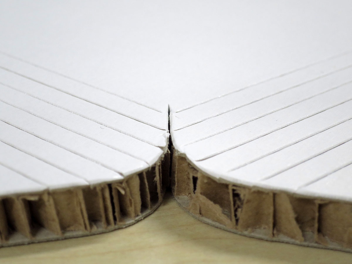
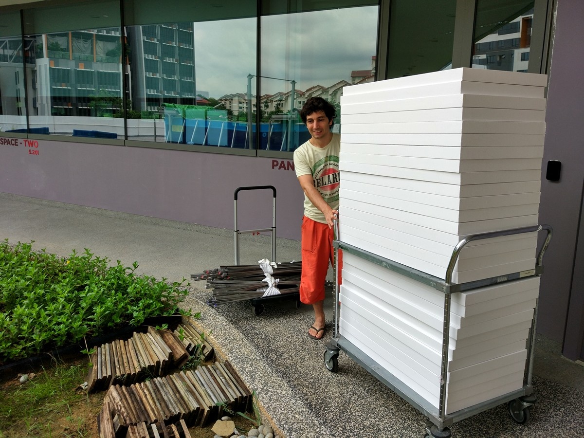
We decided to use D-Board – a high performance honey comb cardboard that is strong and lightweight – for the table top. It comes in 10mm or 16mm thick, 1200mm x 2400mm sheets, with either brown or white core. They are completely recyclable upon end of life. The school has a CNC controlled Zund G3 Cutter that is particularly effective at cutting these boards. We can program it to cut a V groove, through cut or a half cut at a specific depth. This enabled us to cut very complex shapes out of the thick material and create notches and folded joints between the boards and other materials. Sticker-backed digital prints can be mounted on these boards with satisfying surface flatness. Many other projects and exhibitions designed by faculty and students in SUTD have therefore used this material.


The cutter is a 4 axis machine, XYZ plus tool rotation. It can be fitted with a variety of modular cutting attachment (three tools can be mounted at the same time and tool change is automatic). Tool length and alignment is automatic (see the first scene in the video). Material positioning is laser assisted. Among all the possible cutting tools, we used the Pneumatic Oscillating Tool to create through cut and half cut (for blind notches) and the V-Cut Tool for (obviously) V-Cuts.


Legs : 304 SS Rod + DiWire Bender
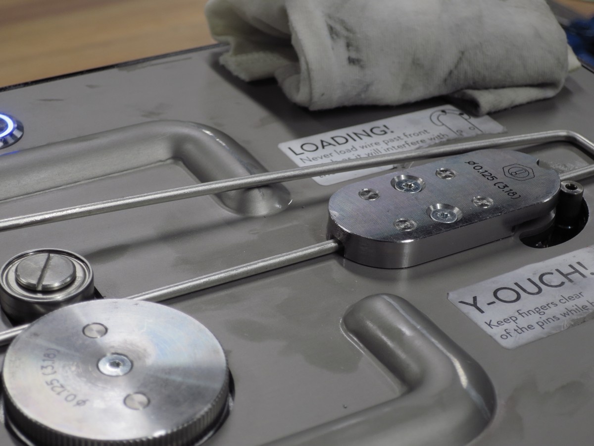
Part of the hidden agenda is to try out a newly available CNC controlled wire bending machine – Di-Wire Bender (Not DiWire Plus / Not DiWire Pro / It was their first model and was now discontinued) . It can bend metals wires up to 3.18mm in diameter and have no problem bending 304 stainless steel. It is a two axis machine (linear feed and bend) that can be easily programmed with a vector file exported in SVG format, with a maximum bending angle of 135 degrees and a precision of about +- 1 degree. It comes at a cost of ~3500 USD and is reasonably easy to setup.
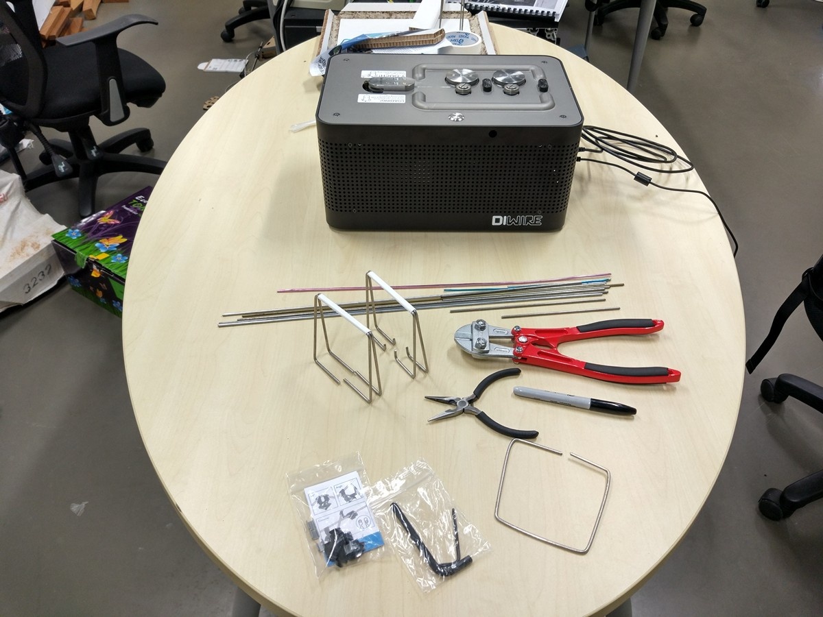
We thought stainless steel would have a pretty nice appearance and should be reasonable strong, so we went for it. A local supplier was able to supply us with the 3.18mm diameter rods in a 2.7 meters length, it came pretty dirty so we polished it with #400 grit sand paper and washed it.

We had to design our table legs to around the machine limitation, which has a maximum bending angle of 135Ëš and a minimum parallel bending distance of 17mm.
Design Statement
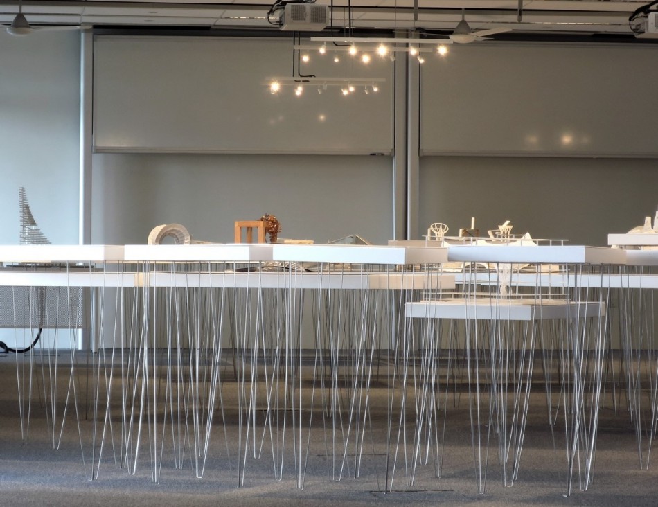
A classical way of conceptually deconstructing a table (I am referring to deconstructivism, not the act of pulling things apart) is that you need legs that can withstand some compression and a table top that can span some distance. Since the D-Board have no problem acting as the table top, the challenge is to see if we can make the legs out of the wires.
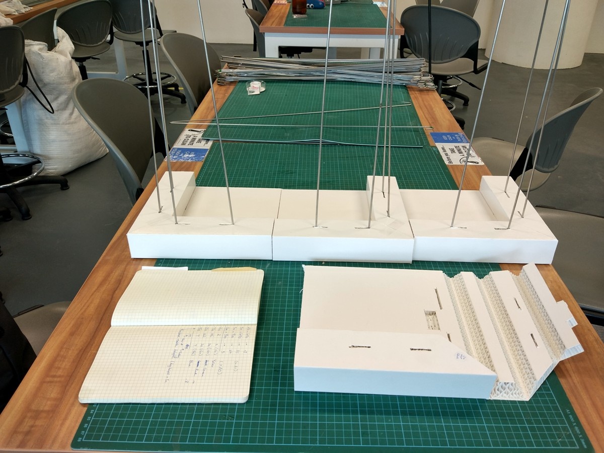
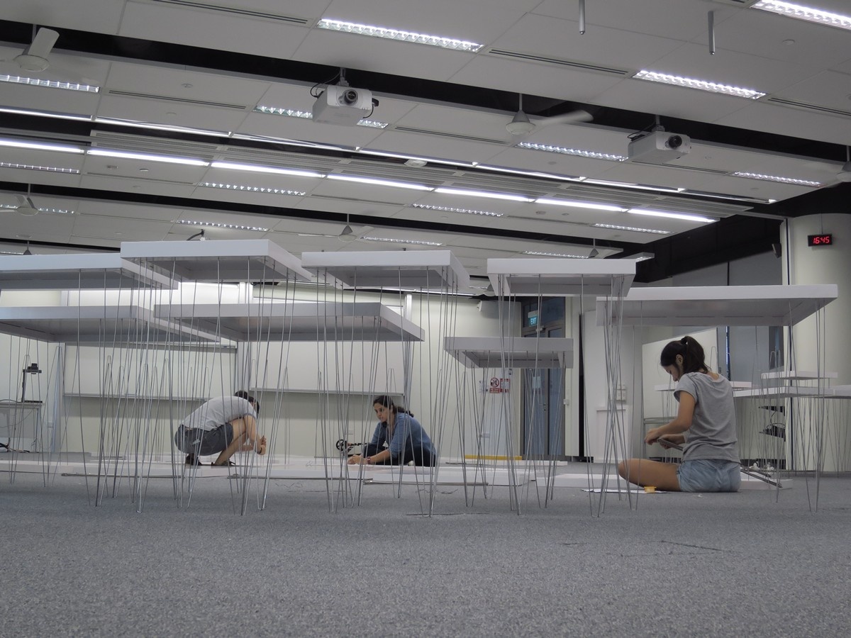
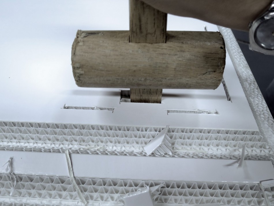
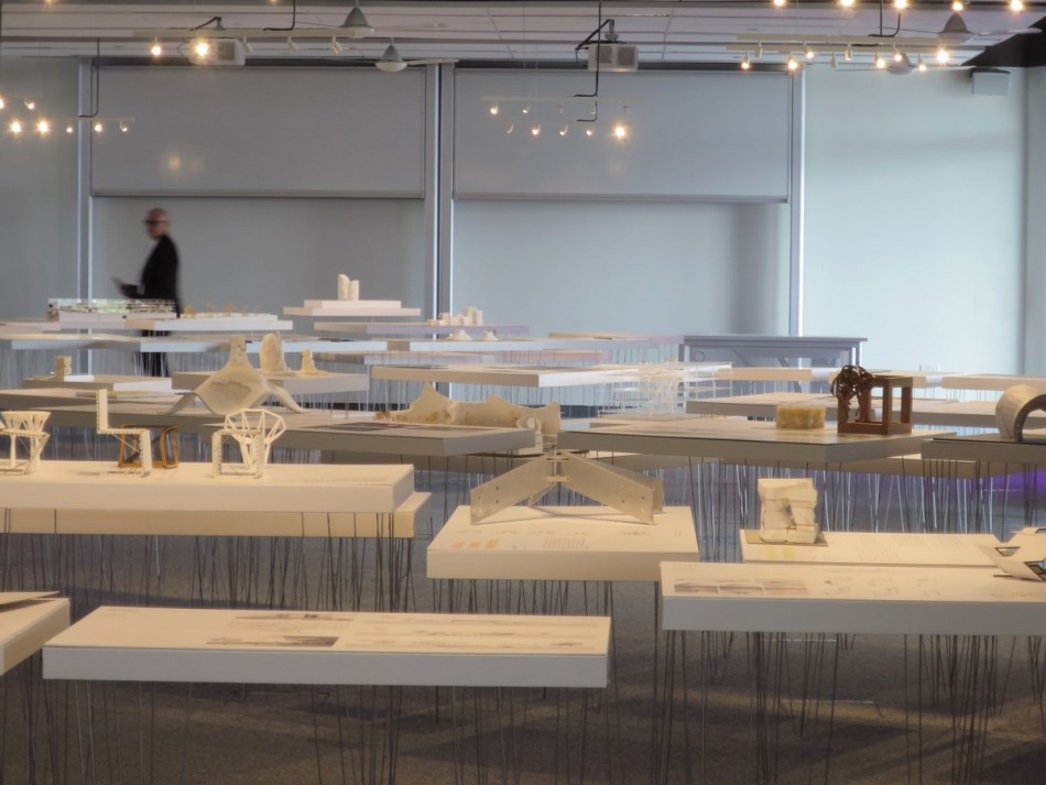
We want our design to emphases the slenderness of the thin stainless steel rods (to be honest, 3.18mm in diameter is so thin that maybe we should call them wires instead of rods). They are pretty flexible on their own and cannot stand much compression without buckling. So we bundled four rods in a double triangular shape to form each table leg. We wanted a pointy triangular tip that touches the ground, but unfortunately the bender cannot bend acute angles, so we have to live with a 17mm wide flat bottom (see the image above: the machine just finished bending the flat bottom). Four legs arranged at the four corners of the table sufficiently held up the heaviest concrete model that is more than 10kg. (Because like every architecture school, some student will cast a concrete model for the sake of it)
We entertained the idea of making a truss structure out of the wires, creating a very strong leg, but that would not have been this beautiful. We also tested if we can weld the 304 Stainless Steel, but I have zero experience in welding and noting fruitful came out of my experiments.
Wire to Cardboard Joint
The tricky part of this project is not just about thin legs standing up. Anyone who have made a table or a chair (that has four legs) will tell you that the connection between the legs and the table top is quite critical. We need to design a joint such that (1) loading will not cause the metal wire to puncture through the cardboard top. And (2) the joint needs to resist bending moment, otherwise the table legs will fail by spreading, way before compression failure. We also need to (3) make the joint easy to assemble and disassemble because we neither have storage space for the assembled tables nor have sufficient on-site setup time before the exhibition opens.

The first major joint design was to use a flat portion of the wire to distribute the load on the cardboard. (See photo below: the leg is very short to save some testing material) The four points that touches the cardboard are forcefully inserted into the board that has a half-cut. This distribution of load worked quite well because the action of forcing the wire into the half-cut slot compressed the honeycomb layer and that gave the wire a stronger bearing surface. However, the insertion jointing method did not provide much resistance against pulling out. This means that when the leg is subjected to bending, one side of the embedded wire will be pulled out from the cardboard. We could of course hot glue/tape the wire as we force it into the cardboard, but that will not allow disassembly and reuse.


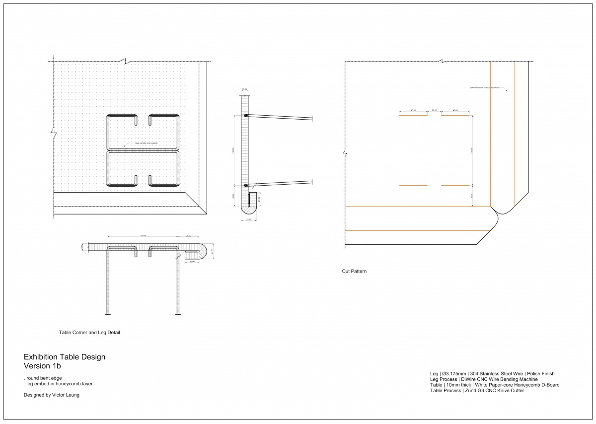
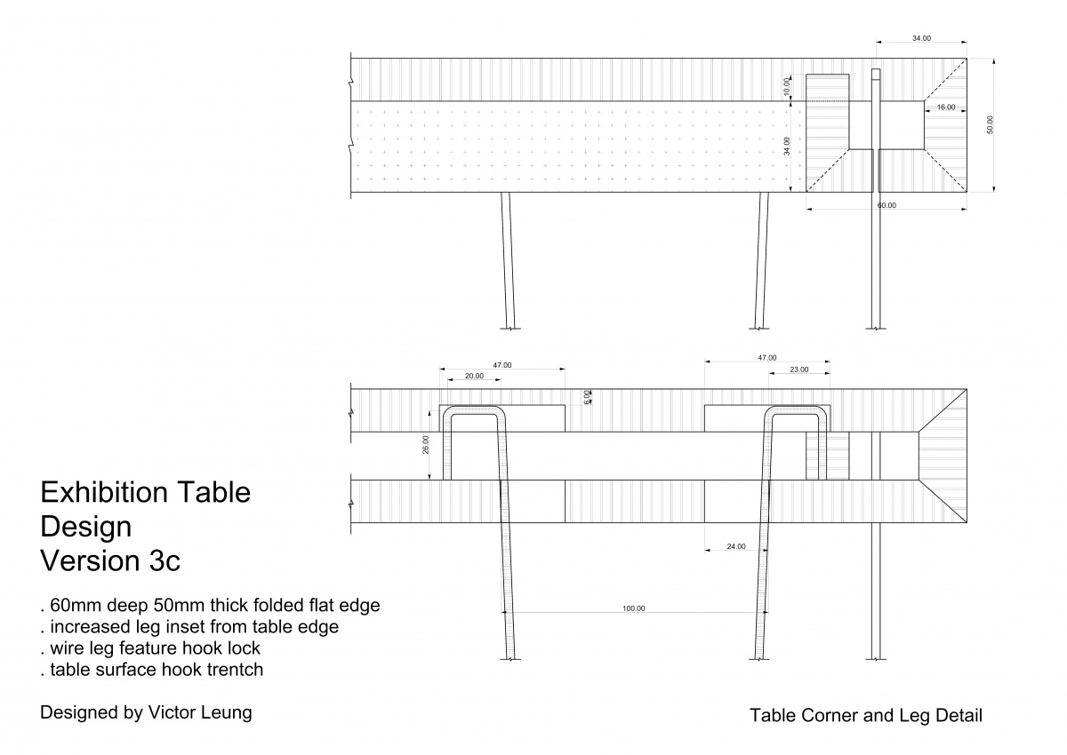
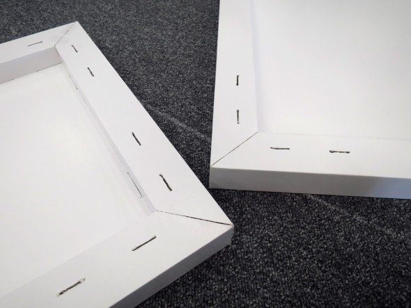
The next important iteration of the joint is to embed the wire at the table edge. This allows each wire to touch the table top at two different levels, giving a tremendous amount of improvement in resisting moment. We kept the flat portion that touches the cardboard top to avoid load induced penetration but we bent the flat part outwards (instead of inwards and complete a ring shape) such that we have two hooks. These hooks then became a mechanism that resist pull-out. (Refer to the Table Corner and Leg Detail drawing below) The leg is inserted through the bottom table edge, forced into the half-cut trench of the table top, and then pushed sideways such it it locks. Simple installation, easy to disassemble, extremely strong joint. (designing this joint feels like designing an Ikea furniture)


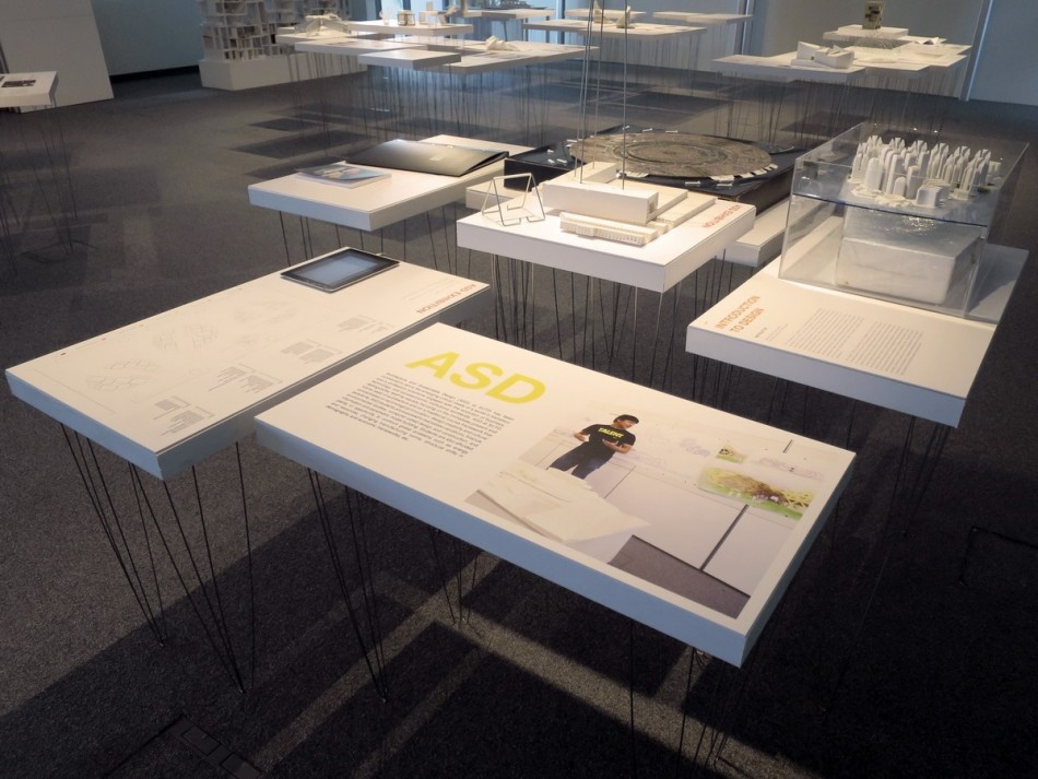
Once we have the joints confirmed, the other development naturally follows. We designed four different table sizes that can effectively hold different content, their dimensions are governed by minimizing cutting waste of the cardboard. We also have five different table height by bending different legs. We added a central rib to our largest table and two extra legs, but I think it is not strictly necessary.


The two triangles of each leg needs to be attached together such that it forms a bundle. Or more structural speak: such that the two wires forms a right angle when viewed on plan, and that makes the wire to table join strong to moment in two different directions. Welding was not an option of us due to the lack of time and tools. In the picture below you see that we just taped it together with white fabric tape, Later on we found that even transparent tape is strong enough, so we went for that. It is hard to notice the tape unless you kneel down and look for it.

Production Details
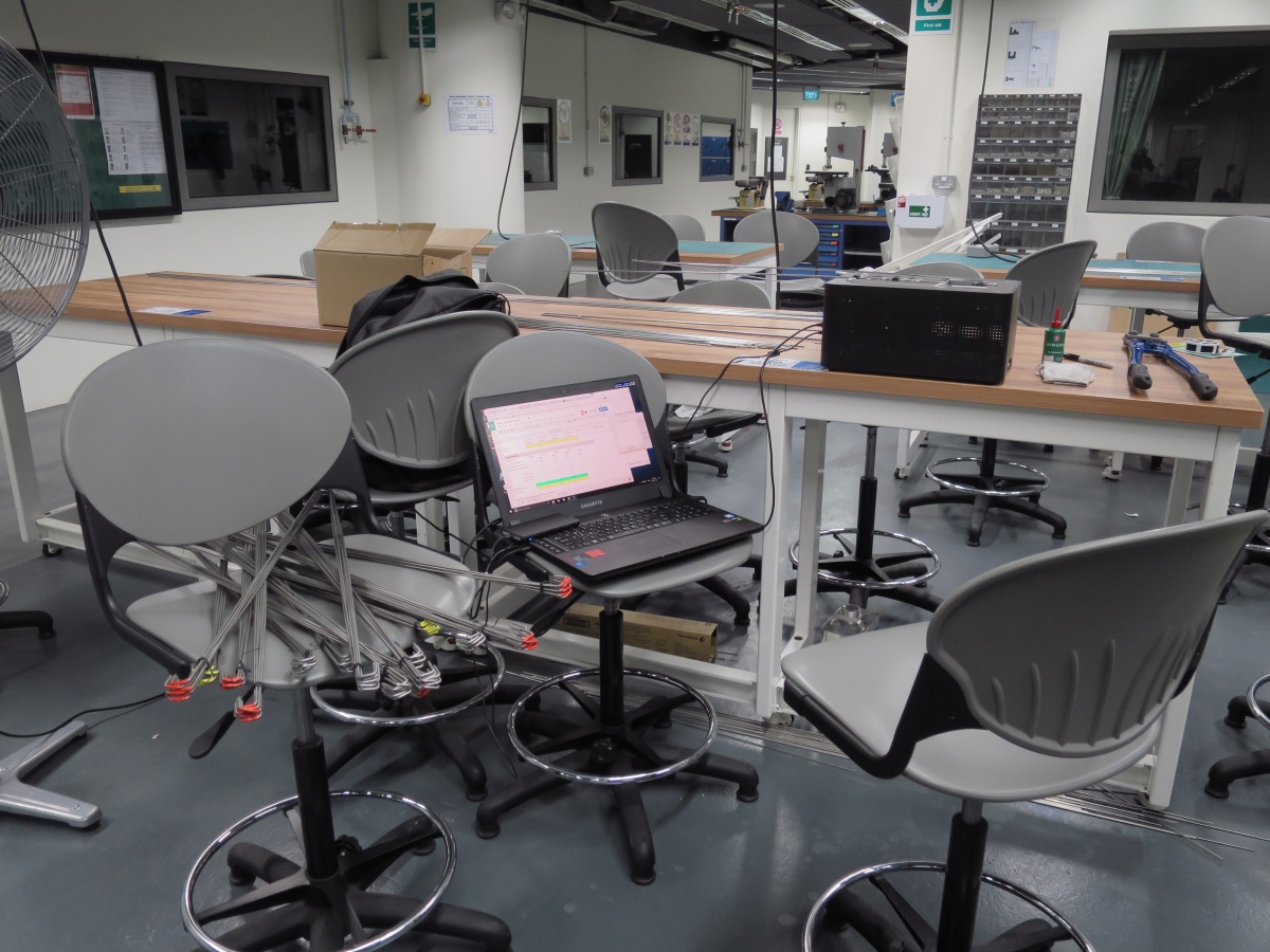
The production of 71 tables was a time consuming process that involved many helpers. We tried hard to optimize the process but there are bottle-necks at certain steps. Polishing the Stainless Steel rods took almost three people two days with a handheld non-orbital sander (supplier does not have better options).

Cutting the tables on the Zund cutter was 20 to 30 hours in total. I couldn’t really complain much. It is what it is.

Cleaning the notches and joints and hot gluing the table edge took three people four to five days. I think if we had cut the pieces with a slower speed and sharper blades (blade change is already quite frequent at 3 sheets per blade) we would have spend less time in cleaning them. The cleaning of the slotted hole could also potentially be done by the cutter by running some tools over it, but we didn’t have time to test that out. We had a rather nice hot glue gun borrowed from the fab lab, very fast heat up and large glue volume per minute (but we had only one, the other one is bad).


Bending the rods with the Di-Wire machine took 15 to 20 hours. About 1 minute per rod with 6 bends each. If there is a automatic wire cutter integrated with the machine, that could have helped. If the wire can come in at longer lengths, we can reduce some waste and saves some loading time. Ideally the machine will be really efficient if it is fed from a spool of wire and pull it through a straightener.


Installation – Site Setup


A little recap of the production parameters:
Table Top Material: Corrugated D-Board (White Paper Core) 16mm x 2400mm x 1200 mm
Machine: ZUND G3 Cutter
Vee Cut Tool: V-Cut Tool / Z73 Blade @ 45Ëš
Straight Cut Tool: Pneumatic Oscillating Tool / Z61 20×1.5mm Blade (4mm left over)
Table Top Sizes: 1300mm x 900mm / 900mm Square / 900mm x 490mm / 490mm Square
Table Leg Material: 304 Stainless Steel Rod Ø 3.18mm (1/8 inch) x 2740mm
Polish: #400 Sanded and Degreased
Table Leg Height: 650mm / 750mm / 850mm / 950mm / 1050mm
Machine: Di-Wire Wire Bender
Tool: Ø 3.18mm (1/8 inch) Bending Attachment
Maximum load: 15kg
Table top and legs are reusable and recyclable.
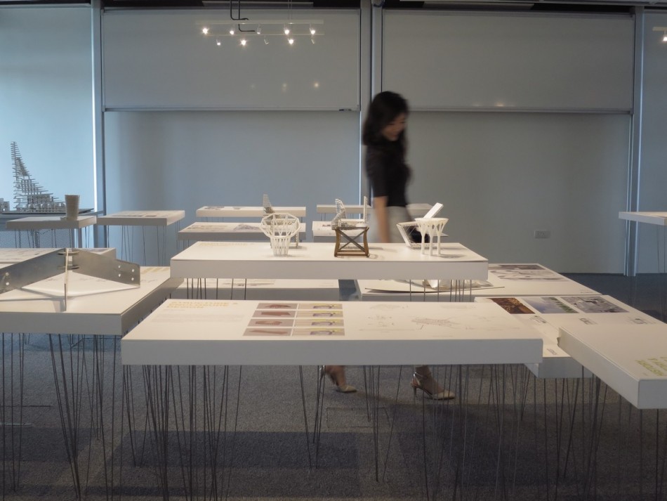
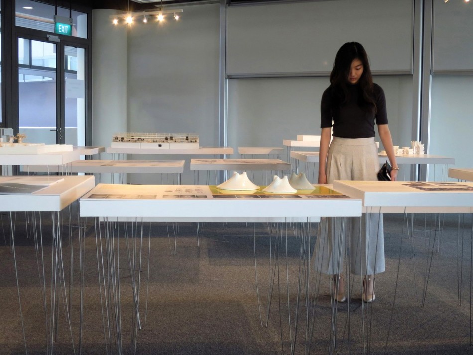
Exhibition Table Design Project for Singapore SUTD ASD 2016 Accreditation Exhibition
Exhibition Photos
 Â
  Â


Team
Design and Fabrication: Victor Leung
Project Lead: Felix Raspall
Exhibition Editor: Vedashree Jathar
Special Thanks to: Ang Yiliang/ Hui Xuan Tan / Kah Wee Lee / Li Jiayi / Tay Jenn Chong / Wang Xiao Tong / Zou Chu Chu

